Back to: UPS Basics
Introduction
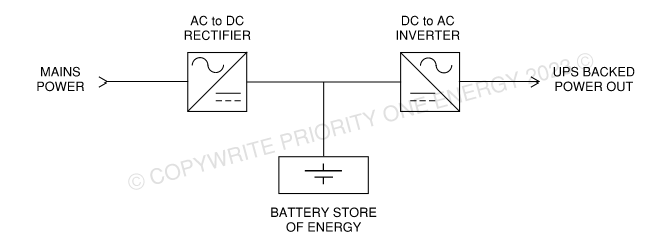
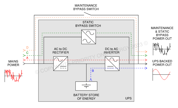
A typical UPS comprises several essential components. The heart of the system is its battery, which stores electrical energy. The mains power supply is converted from AC to DC and then back to AC to serve the loads. When the mains power supply fails, the UPS continues to convert the DC power to AC, but the DC power is supplied from the battery instead of the mains. This ensures 100% continuity of supply as long as there is battery capacity left. See Exhibit 4-1 for a block diagram of these components.
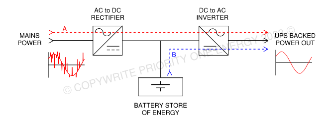
The conversion from AC to DC and then back from DC to AC (known as double conversion) means the UPS provides a high-quality output power waveform in the event that the mains input has poor quality (Exhibit 4-2A) or when the mains power completely fails (Exhibit 4-2B). Power flow is also only in one direction as the rectifier and inverter are not able to reverse/switch their functions.
Static Bypass
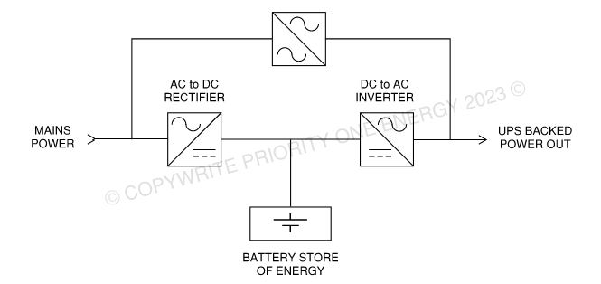
A UPS also includes a static bypass, which is a link that directly connects the mains power input to the output and the loads, bypassing the AC-DC and DC-AC double conversion process. See Exhibit 4-3.
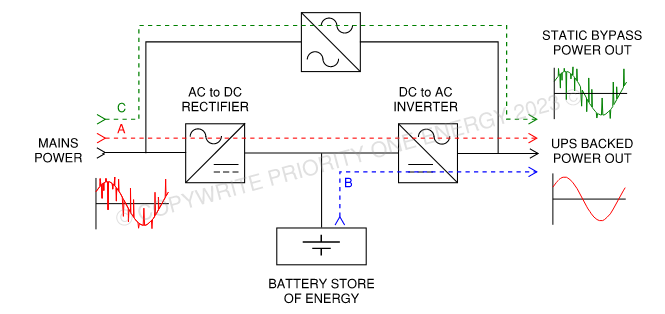
The AC waveform output from the UPS inverter may not be in sync with the mains input meaning if the static invert was closed, it connects two out-of-sync power supplies, cause a fault, and trips the mains’ supply breaker/fuse. To combat the inverter either prevents the static bypass from closing when it is not in sync, or the inverter output is stopped and the static bypass is closed with a very short break (<10ms). This very short break is fast enough that the downstream equipment is not affected. The method used is specific to the UPS manufacturer, but providing the break is less than 10ms, the changeover will be unnoticed by downstream equipment.
When the static bypass is engaged, the mains input is directly connected to the output so all power quality issues are also transmitted to the load, and if during the time on static bypass, the mains were to fail, the inverter output would re-supply the loads (within 10ms). For the static bypass power flow see Exhibit 4-4C.
Maintenance Bypass
The final major component of the UPS is the maintenance bypass. A maintenance bypass is an external component that forms a part of the UPS system, it is not within the UPS itself.
The maintenance bypass allows the whole UPS to be removed from service for maintenance without isolating the power from the loads. Obviously, if there was a failure of the mains while the UPS is undergoing service, the loads would have no protection against the failure.
Exhibit 4-5 shows a UPS system block diagram with an external maintenance bypass and the physical UPS within the grey box. Exhibit 4-5D shows the power flow when the maintenance bypass is closed allowing the removal of the UPS unit (everything within the grey box) without power being lost to the load.
UPS products typically have an internal maintenance bypass, but these do not meet all of the isolation requirements and therefore an external bypass must be provided.
Summary
There are 4 different routes which a UPS back load can be served:
- Path A Mains Double Conversion
- Path B Battery Autonomy
- Path C Static Bypass
- Path D External Maintenance Bypass
Paths A, B and C are automatically selected by the UPS. Path D, external maintenance bypass, is an essential extra route that is needed to allow the maintenance of the UPS itself. Although UPS unit often are marketed as having a maintenance bypass, these are not usually suitable to be used for maintenance so an external must be provided.
Paths A and B will provide a clean output waveform as the output is generated from DC by the Inverter. Paths C and D are directly connected to the mains power so any electrical noise on the main supply will be transmitted to the load.
